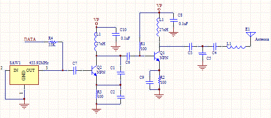
Saw Transmitter Circuit
This circuit uses a saw based oscillator with an output amplifier which drives a transistor. C1 and C2 and L1 are critical oscillator components. They form a tank circuit which should be tuned to the resonator frequency. Typically C1<C2.The output C/L network matches the antenna to the driver.
The tank circuit frequency has the following equation:
F= 1/(2*pi*sqrt(L*C1*C2/(C1+C2)))
Rearranged for L:
L=1/( (2*PI*F)^2 *C1*C2/(C1+C2))
The following calculator can be iteratively used to find appropriate values for the tank circuit.

Saw Transmitter Schematic

