
H-Bridge Latching Relay Driver Circuit
Latching relay driver circuits are more tricky to design than standard relays. In this article were going to look at both the driver circuit for a latching relay and the software considerations. There are several very important nuances that must be considered in order to get it right. Failure to consider these can be very costly, because through neglect you can create circuits that will seem to be working and then find that your microcontroller has unexpectedly died after a few weeks or months.
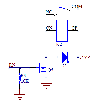
Figure 1: Regular Relay Driver Circuit
First lets look at a standard relay circuit in Figure 1. This is a straight forward circuit, in that the transistor turns on, and the relay coil gets energized. When the transistor turns off the power to the relay is cut, and the coil de-energizes.
The relay coil is an inductor. When power is applied to the coil, current runs through it, and an electric field forms. Inductors don't like it when you try to abruptly change the current flowing through them, especially when the current through them is cut. When this happens the field collapses and a voltage spike forms. As an example, often you will see a spark form when you disconnect a motor or relay. The relay coil as an inductor, wants the current to keep flowing, but it has no place to go.
This voltage spike can cause havoc in other parts of your circuit. For example, it can destroy the transistor, and create a voltage spike on your supply line, and if this is common with your microcontroller, it can destroy it.
The solution is simple. A diode can be placed in parallel with the relay coil. When the relay is turned on, the diode is off and no current is flowing through it. As soon as the relay has power cut to it, the voltage across it's coil increases until the diode is turned on, and the current from the coil flows through the diode in the direction of the diode's arrow, forming a current loop. The current in this loop quickly dissipates and the coil collapses gracefully without a current surge. The diode should have a low forward voltage and be quick to turn on. Diodes in this sort of configuration are called fly-back diodes.
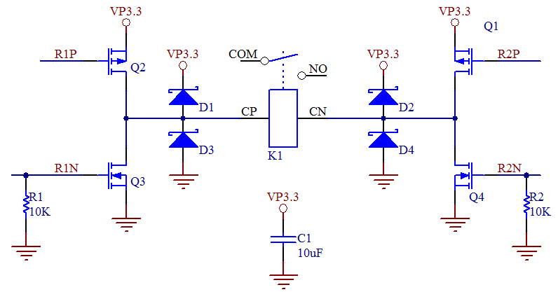
Figure 2: H-Bridge Latching Relay Driver Circuit
The H-bridge latching relay driver circuit is much more complex, but uses the same principles as the simple standard relay driver circuit. Latching relays are useful because they only consume current when their state is changed. Typically a small current pulse or 30 to 60ms is applied to latch them. To change state, a current pulse of opposite direction is applied.
It consists of 4 transistors, 2 P-channel FETs on the high side, and 2 N-channel on the low side. The H-bridge is needed because single coil latching relays require that you reverse the direction of current through them. The resistors on the N channel transistors are used to prevent the gates from floating. When you first power up a microcontroller, the pins can be in an indeterminate state. The resistors prevent this. The circuit also has 4 flyback diodes, which we will discuss in detail.
The first major consideration is that you make sure that your high side and low side transistors on the same side of the bridge never turn on at the same time, otherwise this causes a short from the positive rail to ground, which can surge power consumption, reset microcontrollers, and destroy your drive transistors. This is another reason for the afore mentioned pull down resistors. You want to make sure that when power is applied, that at least one transistor in each leg is turned off, to prevent this short circuit situation.
To apply a pulse of current to the relay, opposite side transistors are turned on. For example, Q2 and Q4 , or Q1 and Q3. When current is cut to the coil one of the 4 flyback diodes will turn on, to form a current loop to dissipate the energy of the coil. The key is that you may only turn off one of the transistors at a time, and then after an appropriate delay, you may turn off the other one. In other words, the remaining on transistor is part of the flyback loop. If you violate this rule, there will be weeping and gnashing of teeth! Let me repeat this, you may not turn off both transistors at the same time, or a current spike will form.
Let's go through one example. Assume Q2 and Q4 are on, and the relay is energized. Turn off Q4. Current is flowing from VP down through Q2, into the relay and out, the current wants to keep flowing and so it must flow through diode D2 back to VP and back to the emitter of Q2 forming a complete current loop, and gracefully dissipating the current and coil energy. If we had cut both transistors at the same time, then the loop would have been broken at Q2, and a current spike would have ensued. You can play this game with any of the transistor pairs, and turn them on and off in any order, and a different flyback diode will be invoked for each case.
It should be noted, that diode configuration handles all 4 cases, but to operate a latching relay only 2 cases are needed. If for example, you always turn off the N-channel FETs first, and the P-channel FETs second. You only need to use the upper diodes, and can simplify the circuit. Using the 4 diodes, make it so your software will work regardless, but if cost is an issue, you can use only 2 diodes to save money if you are careful to use the correct turn on order in software.
To determine the appropriate delay, you can look at your power supply line VP with a scope, If you are seeing a spike, then increase the delay between turning off the transistors, until the spike goes away. In most applications, 1ms is more than enough delay time. You want to use the lowest delay time to conserve power.