How To Measure Inductance
By Tim Daycounter
Most multimeter will measure all electrical properties of a component with the exception of inductance, so you are left to your own devices. There are several methods which we will discuss in this tutorial article.
Method 1 - Impedance Comparison to Resistor
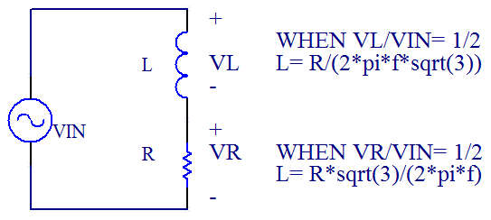
The first is to place the inductor in series with a known resistor of good precision, for example a 100 ohm 1% resistor is a good choice. Stimulate the circuit with a function generator, and view the junction between the resistor and inductor on the scope, as well as the input voltage. Tune the function generator until the junction voltage is half the input voltage. The relationship between R and L is, as derived below.
The advantage of this method is that it is accurate in that calibration resistors can be found with tolerances in the 0.1% range.
If you are measuring the voltage peak to peak voltage across the resistor, then use this equation:
L= R*sqrt(3)/(2*pi*f)
If you are measuring the voltage peak to peak voltage across the inductor, then use this equation:
L= R/(2*pi*f*sqrt(3))
My preference is measuring the voltage across the resistor, instead of the capacitor, because the set up is easier because you can place your scope probes across the resistor, and then swap the inductor or capacitor in and out. Note that the stimulation frequency is 3 times higher when measuring across the resistor, than the inductor. Depending on the frequency range of your equipment, and the self resonance of the inductor, there may be times when one method is preferred over the other.
It should also be noted that this applies for capacitors but the formula is slightly different with R on the bottom, when measuring across the resistor:
C= sqrt(3)/(2*pi*F*R)
Here's a simple calculator:
Derivation of relationship between R and L when |Vo|= 1/2|Vs| when measured across the resistor.
First use the formula for a voltage divider: Vo/Vs= Z1/(Z1+Z2)
Vo/Vs= R/(R+j*w*L)
Next compute magnitude squared by multiplying each by complex conjugate:
| Vo |^2 / |Vs|^2 = | R/(R+w*L) |^2
We care about the Vo/Vs = 1/2:
|1/2|^2 = R^2 / ( R^2+ (w*L)^2 )
4*R^2= R^2+ (w*L)^2
R= w*L/sqrt(3)
L= R*sqrt(3)/(2*pi*f)
Derivation of relationship between R and L when |Vo|= 1/2|Vs| when measured across the inductor.
Vo/Vs= j*w*L/(R+j*w*L)
Next compute magnitude squared by multiplying each by complex conjugate:
| Vo |^2 / |Vs|^2 = | (w*L)^2/(R+w*L) |^2
We care about the Vo/Vs = 1/2:
|1/2|^2 = (w*L)^2 / ( R^2+ (w*L)^2 )
4*(w*L)^2= R^2+ (w*L)^2
R= w*L*sqrt(3)
L= R*/(2*pi*f*sqrt(3))
References:
http://www.edn.com/design/test-and-measurement/4363759/Circuit-measures-capacitance-or-inductance
Method 2 - Resonant Point with a Capacitor.
Another method is to place the coil in parallel with a capacitor of know value to form a tank circuit and then put this tank circuit in series with a resistor of any reasonable value. Then a function generator is used to stimulate the circuit. Place scope probes across the tank, and sweep the function generator, looking for the point of maximum response. This peak value is the resonant point, and a simple calculation can be performed to find the inductance.
L=1/(w^2*C)
The disadvantage with this method is that it's harder to find reference capacitors that have tolerances less than 10%.
Method 3 - Voltage Current Slope
The last method is most complex and requires a that a pulsed voltage be placed across the inductor, and then the current is monitored.The duty cycle of the pulse should be below 50%. Also use a high frequency to avoid saturation. This requires a current sense resistor, or current probe. The current is displayed on the scope and the slope determines the inductance. The slope is the peak current Ipk divided by the on time Ton.
L= V*Ton/Ipk