Title
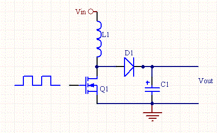
The boost converter is a high efficiency step-up DC/DC switching converter. The converter uses a transistor switch, typically a MOSFET, to pulse width modulate the voltage into an inductor. Rectangular pulses of voltage into an inductor result in a triangular current waveform. We'll derive the various equations for the current and voltage for a boost converter and show the tradeoffs between ripple current and inductance. For this discussion we assume that the converter is in the continuous mode, meaning that the inductor's current never goes to zero.
First, here are some definitions:
| Peak inductor current | ipk |
| Min inductor current | io |
| Ripple Current |  |
| Ripple Current Ratio to Average Current |  |
| Off Duty Cycle |  |
| Switch Off Time |  |
| Average and Load Current |  |
| RMS Current for a Triangular Wave | 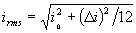 |
The relationship of voltage and current for an inductor is:
 ,or
,or

For a constant rectangular pulse:

From this we can see that the current is a linear ramp, when the voltage is a constant pulse.
When the transistor switches on the current is:
 , or
, or
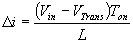
and when the transistor switches off the current is:
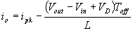 , or
, or
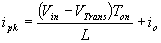
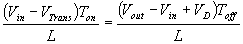
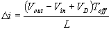 (Equation 1)
Where VD is the voltage drop across the diode, and VTrans is the voltage drop across the transistor. Note that the continuous/discontinuous boundary occurs when io is zero.
By equating through delta i, we can solve for Vout:


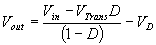
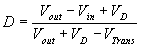
We can also solve for the duty cycle as follows,

If we neglect the voltage drops across the transistor and diode then:

So it is clear that the output voltage is related directly to the duty cycle of the pulses.
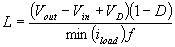
The main question when designing a converter is what sort of inductor should be used. In most designs the input voltage, output voltage and load current are all dictated by the requirements of the design, whereas, the Inductance and ripple current are the only free parameters. It can be seen form Equation 1, that the inductance is inversely proportional to the ripple current. In other words, if you want to reduce the ripple, then use a larger inductor. Thus, in practice a ripple current is decided upon which will give a reasonable inductance.
There are tradeoffs with low and high ripple current. Large ripple current means that the peak current is ipk greater, and the greater likelihood of saturation of the inductor, and more stress on the transistor.
So when choosing an inductor make sure that the saturation current of the inductor is greater than ipk. Likewise, the transistor should be able to handle peak current greater than ipk. The inductor should also be chosen such that the it can handle the appropriate rms current.
It should be noted that when there is a light load the circuit can slip into discontinuous mode, where the inductor becomes fully discharged of it's current each cycle. When a load is reapplied the inductor needs to recharge, and so the transistor's duty cycle increases pulling the inductor towards ground, and because of the increased duty cycle Vout decreases when we really want it to increase. This causes an instability, which is well known for boost converters, and not a problem with buck converters.
One way to combat this instability is to choose a large enough inductor so that the ripple current is greater than twice the minimum load current. When this condition is met then the inductor is always in continuous mode.
This can be expressed as follows:
For higher efficiency the diode should be an ultra fast recovery diode.
These design equations have been incorporated into a convenient Switching Converter Calculator
.